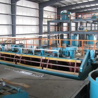
China Good Quality Copper Flotation Cell for Sale
Nanjing Sinonine Heavy Industry Science & Technology Co., Ltd.- Type:Flotation Separator
- Voltage:380V
- Weight:>10T
- Material:Carbon Steel
- Material Feature:Heat Resistant
- Certification:ISO9001:2008
Base Info
- Model NO.:SF,BF,XCF,KYF
- Energy Saving:Energy Saving
- Warranty:1 Year
- Customized:Customized
- Condition:New
- Transport Package:Nude&Wooden Box
- Specification:0.37-100M
- Trademark:sinonine
- Origin:China
- HS Code:8474100000
- Production Capacity:100 Set,Year
Description
Basic Info.
Model NO. SF/BF/XCF/KYF Energy Saving Energy Saving Warranty 1 Year Customized Customized Condition New Transport Package Nude&Wooden Box Specification 0.37-100M Trademark sinonine Origin China HS Code 8474100000 Production Capacity 100 Set/YearProduct Description
Flotation machine is an industrial equipment for the realization of flotation. The key component, inflatable stirring mechanism, determines the type, characteristics and efficiency of the flotation machine. From the view of the process of flotation, flotation machine should have the following functions: 1) so that the pulp is in turbulent state, in order to ensure the suspension agent and ore particles, and to a certain kinetic energy, collision, to achieve attachment of mineral grains and agents; 2) into the air, produce the right size and quantity enough, suitable stability bubble, dispersing in the pulp, the kinetic energy of the particles and chemicals, collision, selective adhesion, achieve mineralization; 3) mineralized bubbles could rise the liquid level, the formation of three-phase foam layer, and two enrichment; foam concentrate and tailings can be discharged in time. There are three kinds of floatation machines commonly used: mechanical agitation type flotation machine, inflatable agitation type flotation machine and inflatable flotation machine. 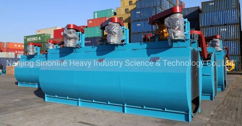
Mechanical agitation type flotation machine
Aeration and agitation pulp is composed of the impeller and the stator mechanical stirring device is completed, belongs to the air self suction flotation machine, is generally the upper gas suction type, namely in the flotation tank at the lower part of the mechanical stirring device near the suction air. According to the type of mechanical mixing device, this type of flotation machine can be divided into different types, such as XJ, XIQ, GF, SF, rod and so on. The advantage of this type of flotation machine is: self suction air and slurry, middling return is easy to realize the self, less auxiliary equipment, equipment configuration and simple operation and maintenance, etc.. Taking the SF flotation machine as an example, the working principle and mechanism of the mechanical agitation type flotation machine are introduced.
The structure of the SF type floatation machine is shown below, mainly composed of the tank body, the spindle unit with the impeller, the motor, the scraper and the transmission device.
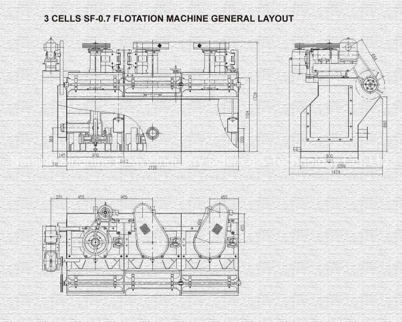
When the SF type floatation machine works, the motor drives the spindle through the V belt to rotate the impeller in the lower part of the motor. The main feature of the flotation machine is shown on the impeller. The impeller has a backward inclined double side blade, which can realize the double circulation of the pulp in the groove. When the impeller rotates, the slurry in the upper and lower impeller chamber produces centrifugal force under the action of the upper and lower blades, namely the main and auxiliary blades, and is thrown to the periphery, so that a negative pressure area is formed in the upper and lower impeller cavity. At the same time, the pulp on the top of the cover plate is sucked to the upper impeller cavity through the circulation hole on the cover plate to form the pulp circulation. The impeller is thrown out of the pulp than the blade throwing out three-phase mixture proportion, thus a large centrifugal force, velocity attenuation is slower, and the three-phase mixture out of the blade generates additional driving force, the centrifugal force is increased, thereby improving the impeller cavity vacuum play auxiliary suction effect. When the lower blade throws out the pulp around, the lower pulp is replenish to the center, thus forming the lower circulation of the pulp. The air is sucked into the upper impeller cavity through the suction pipe and the central cylinder, and is mixed with the pulp of the aspirated person, forming a large number of small bubbles. After stabilizing the flow through the cover plate, the air is evenly dispersed in the tank to form mineralized bubbles. The mineralized bubble floats to the foam layer and is scraped out from the scraper, which is the foam product.
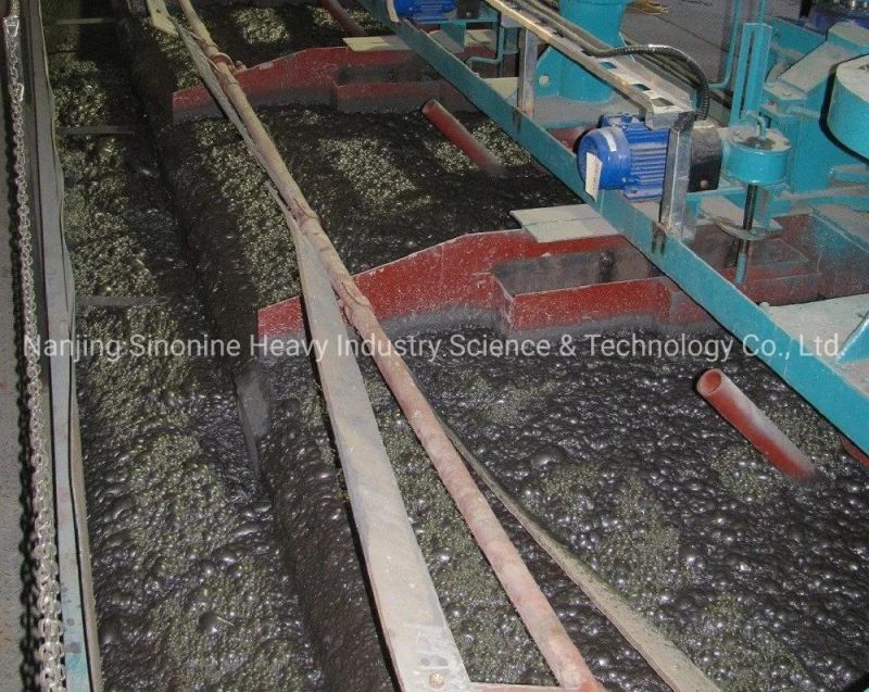
Inflatable stirred flotation machine
It is not only equipped with mechanical mixing equipment, but also forced into the air by the external fan. The mechanical agitation device usually only plays the role of stirring the pulp and the distribution of the air, the air is mainly pressed by the external fan, and the pulp is inflated and stirred. Therefore, this type of flotation machine compared with the general mechanical agitation type flotation machine has the following characteristics: 1) aeration quantity can be increased or decreased, and easy adjustment, maintain a constant, which is conducive to improving the processing ability of flotation machine and selection index; 2) can not afford impeller suction effect, so the low speed, low power consumption, small wear and brittle mineral mud is not easy to produce the phenomenon; 3) due to large capacity, shallow trough and other reasons, the power consumption per unit processing capacity is low. These types of floatation machines have CHF-X, XJC, BS-K, KYF, XCF, BS-K, LCH-X, CLF, etc. aking KYF flotation machine as an example, this paper introduces the working principle and mechanism of the inflatable stirred flotation machine.
The KYF flotation machine is similar to the Otto Quinn F oK type flotation machine in Finland, which absorbs the advantages of the Dorr Oliver flotation machine in the United States. The structure of the KYF type floatation machine is shown in Figure 5. The flotation machine uses U type body, hollow shaft to inflate and suspend the stator, especially a new type of impeller. This is a conical impeller with a backward angle to the blade, which is similar to a centrifugal pump wheel with high specific speed. The pulp is expensive, the pressure head is small, the power consumption is low, and the structure is simple. A porous cylindrical air distributor is also installed in the impeller cavity, so that the air can be dispersed evenly in most parts of the impeller blades, providing a larger slurry air contact interface. When the flotation machine works, as the impeller rotates, the slurry in the tank can be sucked into the impeller blades from the bottom of the impeller through the bottom of the trough, and at the same time, the low pressure air supplied by the blower will also enter the air distributor through the hollow shaft and the impeller. Slurry is fully mixed with the air between the blades, impeller from the upper periphery syncline launched by the stator current and the trough in the backward direction. The bubbles rise to the stable zone of the foam. Through the enrichment process, the foam flows from the overflow weir and enters the foam slot. Some of the pulp flows to the lower part of the impeller, and then agitator by impeller to form a mineralized bubble again. The remaining slurry flows to the next trough until it finally becomes a tailings.
Selection of flotation machine
There are a wide variety of floatation machines, and the following basic principles should be followed when choosing to use.
1)Appropriate type of flotation machine should be selected according to the properties of ore (such as selection, particle size, density, grade, pulp pH, etc.). The mechanical agitation type flotation machine can be selected under the condition that the ore is relatively easy to be selected and the inflatable child is not large. On the contrary, the pneumatic mechanical agitation type flotation machine can be considered. In the coarse granularity processing, can be used for coarse KYF type, BS~K type flotation machine and CLF type coarse flotation machine. In the ore dressing, selected fine granularity, high grade, the lower the pH, can choose the enrichment ratio of flotation column high (especially for cleaning).
2)The flotation machine of corresponding specifications should be selected according to the size of the plant. Generally speaking, large scale flotation plants should be selected for large size flotation machines. Medium and small-sized concentrators should be selected for medium and small size flotation machines, and the specification and quantity of flotation machines should be determined through technical and economic comparison.
3)The main task is to increase concentrate grade and floatation foam layer, so as to separate gangue from the flotation machine. It is not suitable to use the large amount of flotation machine. Therefore, the flotation operation should be different from flotation and flotation.
4)The quality of the floatation machine and the supply of spare parts and spare parts must be paid attention to.
Specification of BF flotation machine
| Model | Cell volume (m³) | Internal dimension (L×W×H)(m) | Air intake (m³/min) | Power (kw) | Capacity ( m³/min) | Single cell weight(kg) |
| BF-1.2 | 1.2 | 1.05×1.15×1.10 | 1.0~1.1 | 5.5 | 0.6~1.2 | 1370 |
| BF-2.0 | 2 | 1.40×1.45×1.12 | 1.0~1.1 | 7.5 | 1.0~2.0 | 1750 |
| BF-2.8 | 2.8 | 1.65×1.65×1.15 | 0.9~1.1 | 11 | 1.4~3.0 | 2130 |
| BF-4.0 | 4 | 1.9×2.0×1.2 | 0.9~1.1 | 15 | 2~4 | 2585 |
| BF-6.0 | 6 | 2.2×2.35×1.3 | 0.9~1.1 | 18.5 | 3~6 | 3300 |
| BF-8.0 | 8 | 2.25×2.85×1.4 | 0.9~1.1 | 22 | 4~8 | 4130 |
| BF-10 | 10 | 2.25×2.85×1.7 | 0.9~1.1 | 30 | 5~10 | 4660 |
| BF-16 | 16 | 2.85×3.8×1.7 | 0.9~1.1 | 37 | 8~16 | 8320 |
| BF-20 | 20 | 2.85×3.8×2.0 | 0.9~1.1 | 45 | 10~20 | 8670 |
| BF-24 | 24 | 3.15×4.15×2.0 | 0.9~1.1 | 45 | 12~24 | 8970 |
Specification of SF flotation machine
| Model | Cell volume (m³) | Capacity ( m³/min) | Impeller diameter (mm) | Impeller speed (r/min) | Power for mixing (kw) | Power for scraper (kW) | Single cell weight (kg) |
| SF-0.37 | 0.37 | 0.2~0.4 | 300 | 352~442 | 1.5 | 0.55 | 468 |
| SF-0.7 | 0.7 | 0.3~1.0 | 350 | 336~384 | 3 | 1.1 | 629 |
| SF-1.2 | 1.2 | 0.6~1.6 | 450 | 312 | 5.5 | 1.1 | 1373 |
| SF-2 | 2 | 1.5 ~3 | 550 | 280 | 11 | 1.5 | 1879 |
| SF-2.8 | 2.8 | 1.5~3.5 | 550 | 280 | 11 | 1.5 | 1902 |
| SF-4 | 4 | 2.0 ~4 | 650 | 235 | 15 | 1.5 | 2582 |
| SF-6 | 6 | 3~6 | 760 | 191 | 30 | 2.2 | 3540 |
| SF-8 | 8 | 4.0 ~8 | 760 | 191 | 30 | 2.2 | 4129 |
| SF-16 | 16 | 5.0 ~16 | 850 | 169~193 | 45 | 1.5 | 7415 |
| SF-20 | 20 | 10 ~12 | 850 | 169~193 | 45 | 1.5 | 9828 |
Specification of KYF flotation machine
| Model | Cell volume (m³) | Internal dimension (L×W×H)(m) | Power (kw) | Min inlet pressure (kPa) | Charge adjustment range (m³/min) | Capacity (m ³/min) | Single cell weight (kg) |
| KYF-1 | 1 | 1.0×1.0×1.0 | 3 | ≥11 | 0.05~1.4 | 0.2~1 | 1056 |
| KYF -2 | 2 | 1.3×1.3×1.25 | 4 | ≥12 | 0.05~1.4 | 0.5~2 | 1346 |
| KYF -3 | 3 | 1.6×1.6×1.4 | 5.5 | ≥14 | 0.05~1.4 | 0.7~3 | 2074 |
| KYF -4 | 4 | 1.8×1.8×1.5 | 7.5 | ≥15 | 0.05~1.4 | 1~4 | 2100 |
| KYF -8 | 8 | 2.2×2.2×1.95 | 15 | ≥19 | 0.05~1.4 | 2~16 | 3857 |
| KYF -10 | 10 | 2.4×2.4×2.1 | 22 | ≥20 | 0.05~1.4 | 3~10 | 4334 |
| KYF -16 | 16 | 2.8×2.8×2.4 | 22 | ≥23 | 0.05~1.4 | 4~16 | 7545 |
| KYF -20 | 20 | 3.0×3.0×2.7 | 37 | ≥25 | 0.05~1.4 | 5~20 | 8240 |
| KYF -24 | 24 | 3.1×3.1×2.9 | 37 | ≥27 | 0.05~1.4 | 6~24 | 9820 |
| KYF -30 | 30 | 3.5×3.5×3.0 | 45 | ≥31 | 0.05~1.4 | 7~30 | 13820 |
| KYF -50 | 50 | 4.4×4.4×3.5 | 75 | ≥33 | 0.05~1.4 | 10~40 | 1056 |
| KYF -70 | 70 | 5.1×5.1×3.8 | 90 | ≥35 | 0.05~1.4 | 13~50 | 26200 |
| KYF -100 | 100 | 5.9×5.9×4.2 | 132 | ≥40 | 0.05~1.4 | 20~60 | 33500 |
Specification of XCF flotation machine
| Model | Cell volume (m³) | Internal dimension (L×W×H)(m) | Power (kw) | Min inlet pressure (kPa) | Charge adjustment range (m ³/min) | Capacity (m ³/min) | Single cell weight(kg) |
| XCF -1 | 1 | 1.0×1.0×1.0 | 4 | ≥11 | 0.05~1.4 | 0.2~0.5 | 920 |
| XCF-2 | 2 | 1.3×1.3×1.25 | 5.5 | ≥12 | 0.05~1.4 | 0.5~1 | 1158 |
| XCF-3 | 3 | 1.6×1.6×1.4 | 7.5 | ≥14 | 0.05~1.4 | 0.7~1.5 | 2172 |
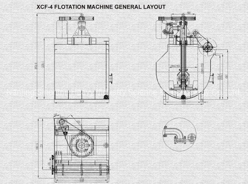
| XCF-4 | 4 | 1.8×1.8×1.5 | 11 | ≥15 | 0.05~1.4 | 1~2 | 2375 |
| XCF-8 | 8 | 2.2×2.2×1.95 | 22 | ≥19 | 0.05~1.4 | 2~4 | 4142 |
| XCF-10 | 10 | 2.4×2.4×2.1 | 30 | ≥20 | 0.05~1.4 | 3~5 | 4894 |
| XCF-16 | 16 | 2.8×2.8×2.4 | 37 | ≥23 | 0.05~1.4 | 4~8 | 6928 |
| XCF-20 | 20 | 3.0×3.0×2.7 | 45 | ≥25 | 0.05~1.4 | 5~10 | 9200 |
| XCF-24 | 24 | 3.1×3.1×2.9 | 55 | ≥27 | 0.05~1.4 | 6~12 | 10820 |
| XCF-30 | 30 | 3.5×3.5×3.0 | 55 | ≥31 | 0.05~1.4 | 7~15 | 14810 |
| XCF-50 | 50 | 4.4×4.4×3.5 | 90 | ≥33 | 0.05~1.4 | 10~25 | 22000 |
| XCF-70 | 70 | 5.1×5.1×3.8 | 90 | ≥35 | 0.05~1.4 | 13~50 | 26200 |
| XCF-100 | 100 | 5.9×5.9×4.2 | 132 | ≥40 | 0.05~1.4 | 20~60 | 33500 |
